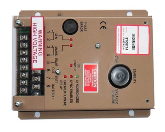
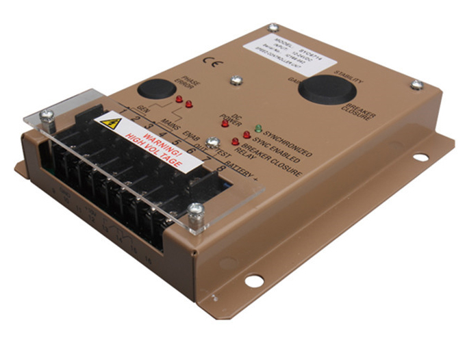
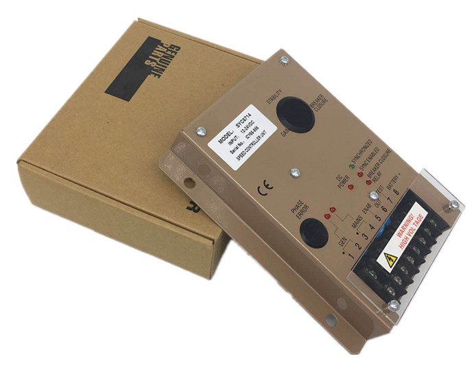
The Synchronizer monitors SYC6714 Control Panel, the phase and frequency of its generator and the main bus. These two AC Signals are electrically isolated from each other and from the governor speed control unit. A phase comparison of the two AC signals is made and a corrective analog DC Signal is generated. This correction signal adjusts the governor speed setting until the electrical phase error between the generator and the main bus is eliminated. With the two AC Signals and the enabling signal at terminal 5, the synchronization process will commence. Any phase error that results may be trimmed out by using the internal“Phase Error adjustment”. When the enable signal at terminal 5 is removed, the synchronizer will assume a neutral output.
Detailed Product Description :
|
Generators and main bus AC inputs |
|
|
Sensitivity |
50 VRMS -500 VRMS (line-to-line or line-neutral) |
|
Frequency |
50 or 60 HZ Normal(400HZ, special order) |
|
Isolation |
1000 V min. |
|
1000 V min. |
less than2.5 VA |
|
BATTERY/DC POWER SUPPLY REQUIREMENTS (TERMINALS 8-10) |
|
|
Low Voltage Range (terminals 8 and 9 connected) |
10-16 V DC |
|
High Voltage Range |
High Voltage Range |
|
Current Required |
less than 200 ma |
|
PERFORMANCE (WITH ESD SERIES) |
|
|
Capture Range |
+4% based on 3250Hz |
|
Output Voltage |
3-7V DC |
|
Breaker Closure Window Size |
-1°-25° |
|
Relay Contact Rating(N.O. or N.C.) |
10A at 28VDC |
|
Phase Error Adjustment Range |
±10°typical |
|
LED's-Synchronization Indicator |
Green LED |
|
Mains |
Red LED |
|
Generator |
Red LED |
|
DC supply |
Red LED |
|
Synchronizer Enabled |
Red LED |
|
Relay Closure |
Red LED |


Contact: Jack
Phone: 0086-19906045242
Tel: 0086-592-7161550
Email: sales@aotchina.com
Add: No.21 Yufu Road, Jimei Disctrict, Xiamen City, China 361000